Barge Flashings in NZ: What They Do, Types, Sizes and Installation
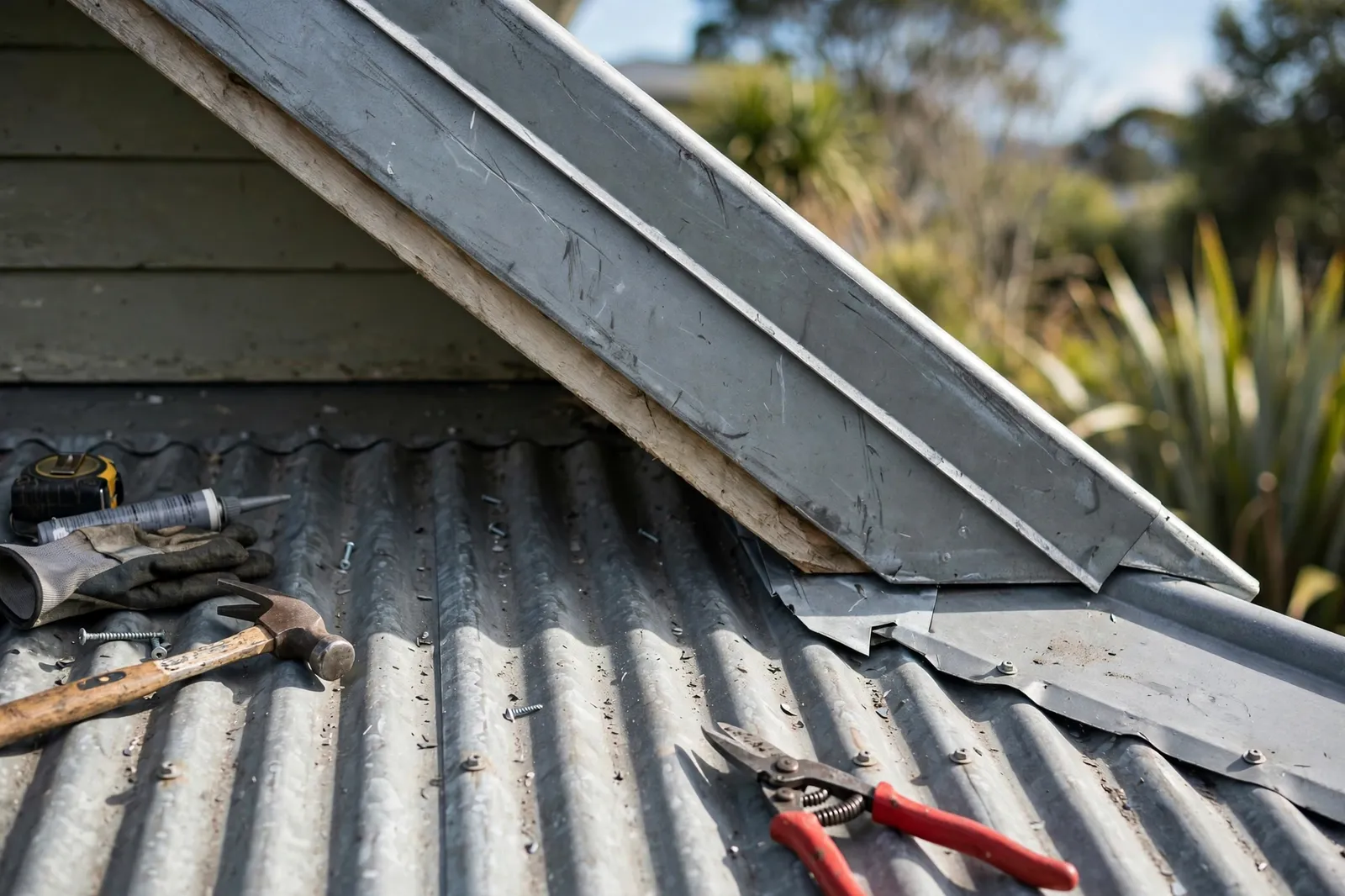
Run your eye up the sloped edge of a gable roof, from the gutter corner to the peak, and you are looking at the barge. It is one of the most exposed lines on the building. Rain arrives there driven sideways by wind, the cut edges of the roof cladding finish there, and the timber board beneath has nowhere to hide if water gets in. The barge flashing is the folded metal cap that closes that edge off. It looks like a simple trimming strip, but its dimensions are set out in the Building Code’s acceptable solution and the metal roofing industry’s code of practice, and getting them wrong is a common way for a sound roof to leak at its edges.
Quick answer
A barge flashing is a folded metal flashing fitted along the sloped edge of a gable roof, where the cladding ends at the bargeboard. It caps the junction between cladding and board, sheds wind-driven rain back onto the roof or down its own face, protects the cut cladding edges from corrosion, and helps hold the edge down against wind uplift. Under E2/AS1, the acceptable solution for clause E2 of the NZ Building Code, the flashing must overlap the barge or fascia board by at least 50mm, 70mm or 90mm depending on wind zone and roof pitch, with its cover over the roofing set by the same table. On metal roofs the detail is governed in practice by the NZMRM Code of Practice and the cladding maker’s own details. Flashings are folded to order, and makers publish dimensions and fixing guidance but no prices.
What a barge flashing is, and where it sits
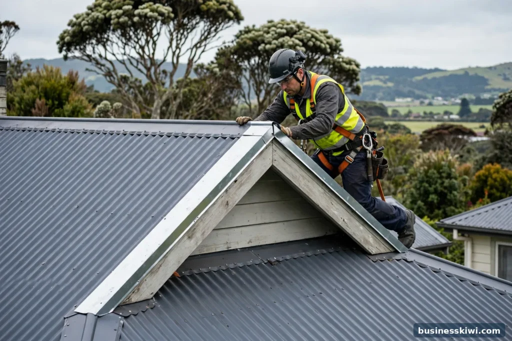
Every gable roof has two sloping edges where the roof plane ends and drops to the gable wall below. The board fixed along that slope is the bargeboard. The barge flashing sits over the top of that junction. One leg of the fold lies across the top of the roof cladding, covering its cut edge. The fold then turns down the outside face, covering the top of the bargeboard and finishing partway down it, so water is thrown clear of the timber.
The barge is the sloping partner of the eaves edge. Where the barge runs up the slope, fascia boards run horizontally along the eaves, carrying the gutter and closing the roof’s bottom edge. Both edges need the same treatment: adequate cover, a drained path for water that gets underneath, and fixings into structure.
Terminology varies a little. Verge is the term used more in Britain for the same edge. A barge board cover can be just the downstand face piece over the board, while a barge flashing proper is the full folded section that also extends over the roofing. On most roofs the two are combined in one profile.
The jobs the flashing does
The first job is shedding water. Rain on a gable edge does not politely run downhill. Wind pushes it across the slope and up under any lip it can find, and the NZMRM Code of Practice points out that the pressure difference between the outside of a longitudinal flashing and the space behind it is what drives ingress. A small gap behind the outer edge acts as a pressure cushion and breaks capillary action, which is why a correctly folded barge is not simply clamped flat and sealed along its edge.
Second, it protects vulnerable material. The cut edge of a coated steel sheet is its weakest point for corrosion, and the end grain at the top of a timber bargeboard drinks water readily. BRANZ describes flashings as working on two levels: a primary defence that stops moisture getting through the envelope, and a secondary defence that drains out any moisture that does get in. Maker details show the roof underlay continuing over the wall underlay at the barge, so anything reaching it still drains outside the wall.
Third, the flashing is structural in a small way: the Code of Practice notes that barge and verge flashings help hold the cladding down under high peripheral wind loads, and where they are omitted the roof must be designed for uplift on both surfaces of the cladding edges.
What failure looks like
Barge failures rarely announce themselves with a dramatic drip. Wind-driven rain works under a flashing with too little cover or no stop end, wets the top of the bargeboard and the battens behind it, and the timber rots where nobody inspects. Cut sheet edges left exposed corrode back from the edge, and tracked water can surface as staining at the top of the gable wall, well away from the entry point.
On the metalwork itself, the tell-tale faults are mechanical. Long runs fixed rigidly cannot move as the metal heats and cools, and the Code of Practice warns that riveted joints are prone to popping from thermal expansion and timber shrinkage. Sealant smeared over the outside of a joint, rather than sandwiched inside it, peels away, leaving the appearance of a seal with none of the function. Incompatible metals in contact, or runoff from one metal washing over a less noble one, set up galvanic corrosion that eats through thin flashing material years early.
The rules: clause E2 and E2/AS1
Clause E2 of the NZ Building Code, External Moisture, requires buildings to resist the penetration and accumulation of external moisture, and to let any moisture that does get in dissipate without damage. MBIE’s Building Performance site explains that E2/AS1 is the Acceptable Solution for the clause, widely used for timber framed buildings, and that following an acceptable solution is deemed to comply with the Code. BRANZ summarises the Code definition of flashings as components that drain or deflect water back outside the cladding system, required at junctions and edges, barges included.
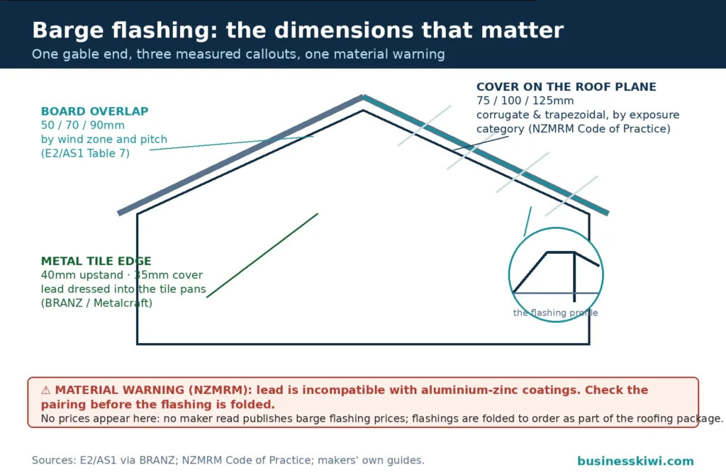
BRANZ’s Build magazine guide to roof flashings sets out the E2/AS1 barge dimensions from Table 7 and Figure 47. The overlap over the barge or fascia board is 50mm minimum in low, medium and high wind zones where the pitch is 10 degrees or more, 70mm where the pitch is 10 degrees or less in those zones and at all pitches in very high wind zones, and 90mm at all pitches in extra high wind zones. Cover over the roofing follows the apron flashing rules for flashings parallel to the slope: for profiled metal roofing, over at least two crests of the profile; for clay and concrete tiles, 150mm minimum with a lead flashing dressed down into the tile pans; for metal tiles, a 40mm minimum upstand and 35mm minimum overflashing cover. The hem rule: in low through very high wind zones a hem or hook on the upstand can be traded for an extra 25mm of upstand height, while in extra high zones both are required.
BRANZ cautions that E2/AS1 has been amended since its article was published, so the current version on MBIE’s site is the document to check for a specific project. In practice, most metal roofs here are detailed using the maker’s own tested details and the NZMRM Code of Practice alongside E2/AS1.
Cover dimensions at a glance
Three documents do most of the work on barge sizing, and they measure slightly different things. E2/AS1 measures the overlap down over the barge board. The NZMRM Code of Practice measures cover over the cladding surface, on smooth and profiled surfaces, plus the number of profile upstands crossed. Dimond Roofing publishes its own effective minimum cover table. The Code of Practice is clear that weathertightness is determined by the cover achieved, not the overall dimension of the folded flashing. Its exposure categories run from A (low to high wind zones) to D (specific design wind zones up to 68 metres per second).
Materials and profiles
Flashings are folded from flat sheet, and the default rule from both the Code of Practice and the manufacturers is that exposed flashings are made from the same base metal as the cladding, colour matched through the same manufacturer and process as the roof. The flashing has to last at least as long as the cladding it trims. Code of Practice minimum thicknesses are 0.55mm for coated steel, 0.70mm for aluminium, 0.60mm for copper, 0.70mm for zinc and 0.45mm for stainless steel. Dimond’s own specification uses 0.55mm G300 steel and 0.9mm aluminium, with copper and stainless on request. Copper turns up on older and higher end work, but it sits high in the galvanic order, so its runoff must be kept away from zinc and aluminium coated steel below it.
Profile shapes are variations on an L or Z fold with a turned edge. Steel & Tube’s product guide names its common barge forms as soft edge, birds beak and standard barges, noting that corrugate barge dimensions may be branch standard, with other profiles specified by the installer. The soft edge uses a flexible strip dressed over the roofing profile to close the corrugation gaps. The birds beak turns the outer edge back on itself to form a stiff, drained drip.
Wide flat faces oil can, the visible waviness thin sheet develops, so the Code of Practice caps unstiffened flashing width at 300mm and recommends no more than 200mm of unstiffened depth on a vertical face such as a barge. Dimond limits flashing girth to its 1219mm coil width and recommends a maximum length of 6 metres.
How the detail changes with the cladding
Long-run metal roofing
On corrugate and trapezoidal roofs the sheet ends are the starting point. Dimond requires all cladding profiles to be stop ended at the top end of the sheet on all pitches, and the Code of Practice requires stop ends on flashings for all pitches in all wind zones, because an open profile end at the barge is a funnel for wind-driven rain. The barge flashing then covers the sheet edge by the rib or corrugation counts in the table above. On non-corrugate profiles where two rib cover is required, Dimond specifies at least one full rib plus the trimmed sheet edge turned up to the full height of the rib, and a turned up edge to full crest height counts as a crest in its own right.
Pressed metal tiles
Metal tile roofs finish their gables differently, because the cladding arrives in short pressed pans rather than long sheets. Metalcraft Roofing’s install guide offers two gable finishes, angle caps or folded barge flashings, with cap tiles bent on site to form the flashing. The tiles are turned up a minimum of 40mm against the batten running up the barge, and the cap or flashing must cover those turn-ups by at least 35mm, figures Metalcraft ties back to E2/AS1 and the NZMRM code. The set-out is unforgiving: vertical battens are installed for the flashings to fix to, 70mm from the outside of the batten to the outside of the barge board with a standard 20mm barge board, and the combined thickness of the extra batten and the barge must be 65mm. Standard flashings come in 1.5 metre lengths, painted flashings in 2 metre lengths, joints undersealed and fastened with coloured rivets. End trim and stop ends at the bottom are formed from an offcut of tile.
Concrete and clay tiles
Heavyweight tiles use their own components rather than a folded metal barge in most cases. CSR Monier’s NZ installation guide describes its A+B barge and gable finish, where standard or rounded barge tiles are laid over the gable end, with or without bedding, and the lower end of the barge tiles mechanically fixed into the barge board or brickwork. Its bed and point finish instead lays a fibre cement bedding strip 100mm wide and 5mm thick over the barge board, projecting 19mm to 25mm beyond the board’s face, with mortar bedding on the strip and flexible pointing to finish. Metal still appears at the margins: Monier’s drawings show a Z flashing under the fibre cement strip, sized according to wind zone, a further Z flashing where the tile’s over-roll upstand cannot be achieved, and an option for a pre-primed 75mm metal capping. Monier is explicit that cement mortar alone is not a mechanical fixing method. Clay tiles follow the same family of details.
Membrane and shingle roofs, in outline
Low slope membrane roofs and asphalt shingle roofs are less common in New Zealand, and their gable edges are normally closed by the system’s own edge metal. BRANZ’s guidance on cap flashings for membrane work requires metal and membrane caps to have no penetrations and to overlap the claddings on both sides by 50mm, 70mm or 90mm across the same three E2/AS1 situations.
Laps, lengths and joints
A long barge is rarely one piece of metal. Lengths are joined with laps, and the Code of Practice lap rules are strict. Water must always flow over a lap, never into it, so laps face downhill and downwind where possible. A lap must not rely on sealant alone. Sealed laps are mechanically fixed at 50mm centres, unsealed laps need at least 150mm of cover, and 100mm is the recommended minimum for sealed laps. Metalcraft’s tile guide uses the same 100mm figure.
Length itself is a design decision. The Code of Practice puts the preferred maximum production length at 6 to 8 metres, and warns that a sealed, riveted lap effectively turns two lengths into one, so expansion joints are needed on long runs. Dimond advises that where several 6 metre lengths are lapped and joined, expansion must be accommodated once the total exceeds 18 metres in steel or 12 metres in aluminium.
Fixings, sealants and movement
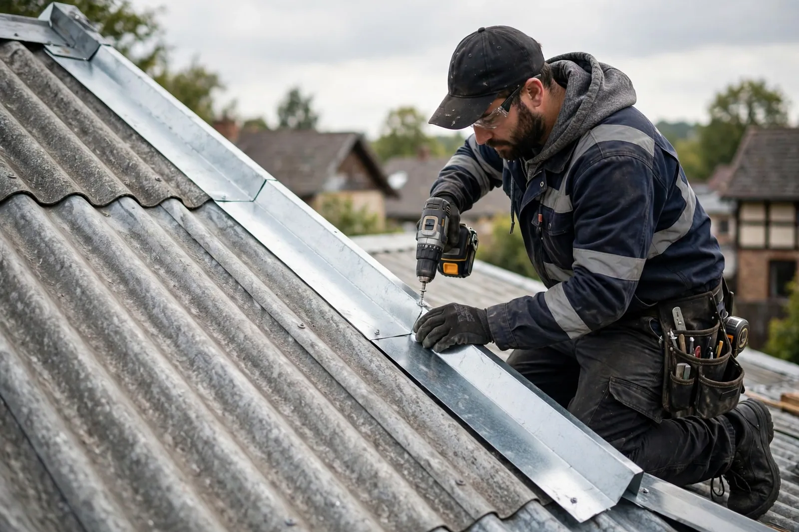
The Code of Practice divides flashing fixings into primary fixings into the main structure, secondary fixings into the cladding, and clips, cleats or seams that allow differential movement. At least one row of fasteners should reach the primary structure, sitting within 25mm of the exposed edges, on both edges, spaced to each structural member crossed. Dimond agrees the primary fastening must penetrate through to the supporting purlin or girt, and gives barge spacings directly: on a barge or parapet in low and medium wind zones, vertical face fasteners go at no more than 1 metre centres, tightening to 500mm maximum in high wind zones and above. Secondary fixings are stitching screws or rivets, with sealing washers except under rivets, which must themselves be sealed or self sealing. Dimond sets a minimum diameter of 4.8mm for aluminium rivets. Cleats, an under-flashing the flashing hooks onto without direct fixing, allow movement.
Sealant has a narrower role than most people assume. The Code of Practice specifies neutral cure silicone or MS polymer sealants, and states flatly that acid cure sealant must not be used. Any design using sealant must always include mechanical fastening. Sealant works when sandwiched inside the joint; post applying it to the outside of a finished joint is described as futile and unacceptable. Inside a compressed lap the sealant width should not exceed 25mm, applied as a bead of about 6mm diameter.
Compatibility runs through all of this. Flashings must suit the cladding for contact and runoff, hidden flashings must last the life of the building or at least 50 years, and flashing edges must not sit in wet contact with concrete, plaster or butyl rubber. One trap is soft edging: lead, the traditional material, is incompatible with aluminium zinc coated steel, so the Code of Practice points to soft aluminium or composite alternatives. Above a 30mm profile, notched edging is preferred, and scribed edges need 2mm to 5mm of clearance so the moving sheet does not abrade its coating.
The two ends of the barge
At the top, the barge meets the ridge. On metal tile roofs Metalcraft closes the junction with end caps made from offcuts, riveted inside the front edge of the cap. On long-run roofs the ridge and barge flashings are lapped and sealed so water cannot track sideways at the apex. At the bottom, the barge finishes above the gutter, where stop ends close the profile and the flashing so wind cannot pressurise the space underneath and drive rain uphill.
Common mistakes
Most barge failures trace back to a short list of avoidable errors:
- Cover skimped to save a fold, leaving less than the Table 7 or Code of Practice cover for the wind zone and pitch.
- Sealant treated as the waterproofing, smeared over a joint with no mechanical fixing behind it.
- Missing stop ends at the top of sheets or the bottom of the barge, leaving the profile open to wind-driven rain.
- Mixed metals, such as lead soft edging against aluminium zinc coated steel, or copper runoff over zinc based cladding, causing galvanic corrosion.
- Fixings that only reach the cladding, not the structure, on the edge of the roof that sees the highest wind pressures.
- Flashing faces folded too wide without stiffening, which oil cans and ponds water. Dimond requires at least a 3 degree fall on all flashing surfaces, and no plane wider than 300mm without ribs or support.
Ordering and cost
There is no standard shelf product to price. Barge flashings are folded to order from coil for the profile, pitch and girth each roof needs, and are sold through roofing merchants and installers as part of the roofing package. None of the manufacturers whose documents inform this guide publishes a price for barge flashings on its own pages, so this article gives no prices rather than borrow a retailer’s figures. Cost turns on the material and gauge, the girth of the fold, and the number of lengths and joints.
Frequently asked questions
What is the difference between a barge flashing and a fascia?
They close different edges of the same roof. The barge flashing runs up the sloped gable edge over the bargeboard, while the fascia runs horizontally along the eaves and carries the gutter. Both cap the junction between cladding and board.
How much cover does a barge flashing need in New Zealand?
Under E2/AS1 the overlap over the barge board is 50mm in low, medium and high wind zones at pitches of 10 degrees or more, 70mm at lower pitches and in very high wind zones, and 90mm in extra high wind zones. The NZMRM Code of Practice separately sets cover over the cladding surface: for corrugate, 75mm over a profiled surface in its lowest exposure category, rising to 125mm in the highest, crossing two or three profile upstands depending on category.
Can I use lead soft edging on a Colorsteel or Zincalume roof?
No. The NZMRM Code of Practice states that lead is incompatible with aluminium zinc coatings, which are the coatings used on those products. Soft aluminium or composite edging is the alternative it offers.
Does a tiled roof need a metal barge flashing?
Usually the gable is finished with the tile system’s own components. Monier’s NZ guide uses standard or rounded barge tiles over the gable end, mechanically fixed at the lower end, or a bed and point finish over a fibre cement strip. Metal still appears as Z flashings under the strip, sized by wind zone, and as an optional capping. Metal tile roofs use angle caps or folded barge flashings over tiles turned up at least 40mm, with at least 35mm of cover over the turn-ups.
Who is allowed to install or replace barge flashings on a house?
Flashings are part of a home’s weathertightness system. MBIE explains that restricted building work, residential work needing a building consent that affects a home’s structure or weathertightness, must be carried out or supervised by a Licensed Building Practitioner, and roofing is one of the licence classes. Whether a particular repair counts depends on the consent position. An owner-builder exemption exists for homeowners doing restricted work on their own home with council approval.
Sources
MBIE Building Performance, E2 External Moisture, building.govt.nz
BRANZ Build, Roof flashings, buildmagazine.org.nz
BRANZ Build, Flashing Supplement (Build 162), buildmagazine.org.nz
NZ Metal Roofing Manufacturers Association, NZ Metal Roof and Wall Cladding Code of Practice, section 8 Flashings, metalroofing.org.nz
Dimond Roofing, Flashings and Flashing Design, dimond.co.nz
Dimond Roofing, Flashings technical document, dimond.co.nz
Steel & Tube, Roofing Solutions Product Guide, steelandtube.co.nz
Metalcraft Roofing, Metal Tiles Install Guide, metalcraftgroup.co.nz
CSR Monier, NZ Monier Installation Guide, csrassetlibrary.com
MBIE Building Performance, Restricted building work, building.govt.nz
Disclaimer
This article is general information about barge flashing practice in New Zealand, not project specific advice. Flashing design for a particular roof should follow E2/AS1 or the cladding manufacturer’s own tested details for the profile being used, and the current version of the acceptable solution should be checked for any specific project. The dimensions quoted are the published figures of the bodies and manufacturers named, summarised for explanation, and do not replace the source documents. Where flashing work forms part of restricted building work on a home, it must be designed and carried out or supervised by a Licensed Building Practitioner as MBIE describes.
For more technical explainers on the materials and components that go into NZ buildings and businesses, see our Business & Industry guides.